
Logic Gate Simulator
Build and simulate digital logic circuits with AND, OR, NOT, XOR gates, LEDs, and clock signals.
About Logic Gate Simulator
Place gates on a canvas, wire them together, and watch voltage flow in real time. Logic Gate Simulator lets you build digital circuits from scratch using the fundamental components — AND, OR, NOT, XOR gates, LEDs, and clock signals — then toggle inputs and observe exactly what happens. It's hands-on in a way that textbook diagrams never quite are.
This is genuinely useful for students working through a computer architecture or electronics course, but it's just as approachable if you're simply curious how binary logic underlies every chip ever made. Start with a basic AND gate and a couple of input switches, or attempt a half-adder if you already know your way around a truth table. The open-source MIT-licensed codebase is available if you want to dig deeper. Browse more apps like this in education.
If numbers and graphs are more your thing, Graphing Calculator goes in a different direction but covers the same hands-on STEM territory. For Logic Gate Simulator itself, a larger screen is worth it — the wiring canvas gets crowded fast once you add more than a handful of gates, and tracing signal paths is much easier when each connection has room to read clearly.
Look inside
How to use
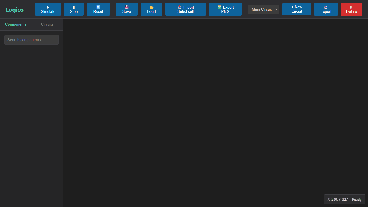
Build and test digital logic circuits using drag-and-drop components and real-time simulation. **Basic Setup:** 1. Drag logic gates from left palette onto canvas 2. Connect components by dragging from output pins (circles) to input pins (squares) 3. Click "Simulate" to start real-time circuit evaluation **Mouse Controls:** - Left-click: Select components/wires - Ctrl+click: Multi-select items - Drag: Move selected components - Right-click+drag: Pan workspace - Mouse wheel: Zoom in/out - Double-click input pins: Toggle on/off states - Click+drag on empty space: Draw selection box **Keyboard Shortcuts:** - Delete: Remove selected items - Ctrl+A: Select all - Ctrl+C/V/X: Copy/paste/cut - Escape: Clear selection **Key Features:** - Components snap to grid automatically - Active wires highlight during simulation - Create reusable subcircuits with "New Circuit" - Save/load entire projects - Visual feedback with LEDs and wire highlighting **Goal:** Design functioning digital circuits by connecting logic gates and testing with interactive inputs and visual outputs.
Reviews
No written reviews yet. Be the first!
More from Education

A geography speed-quiz. Type country names against the clock — every one you nail lights up the map. Eight maps (world + every continent), three paces, leaderboards, percentile standings, and a per-answer rarity stat that shows how many other players named each country.
by geodude


